It all started a few months ago when I put together a TDA1541+OPA49720 schematic on an experimental board along with a regulated PSU based on LM317/337. The plan was to push the digital signal from PCM2707 to the TDA1541 via I2S. The moment I started this thing I was immediately amazed by the sound of TDA1541, it sounded very warm to my ears and I decided I need to finally build a proper USB DAC, as I listen to all my music collection(FLACs,APEs,WAVs) with my PC as a source.
However, at that time I didn’t have enough time to continue with this project so I put everything in a cupboard and now I decided to finish it finally. The schematics were revised and SPDIF input is now planned along with the USB so DIR9001 is needed.
I found a nice PCB(thanks to Simonov) from my favourite forum Bgaudioclub to move over the parts from the experimental PCB as a PCB is always a better option, especially for audio/video circuits which can easily “catch” RF noises.
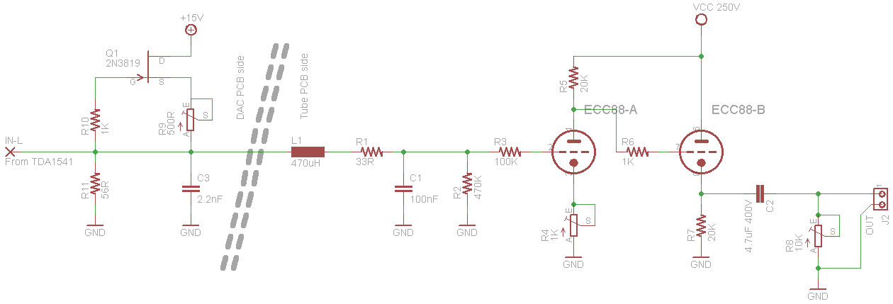
Click for the first part of the DAC schematic (before the tubes).
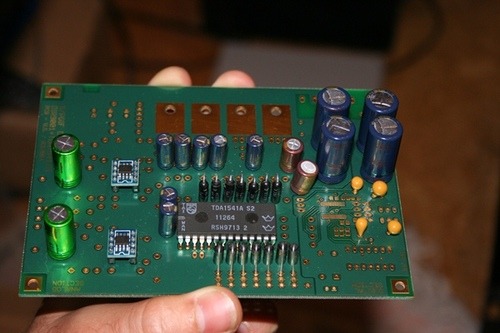
PCB picture:
A forum mate’s implementation as mine is not ready yet. Pictures of my DAC coming shortly.
As for the tube stage I decided to use a CCDA circuit inspired by a post in the diyAudio forum. The SK170 is used to null out the DC voltage offset in the output of the TDA1541. As you can figure out, the OPAMP section of the board above can be obstructed when using a tube output stage like the one I’m writing about. Here is my redraw of the circuit. The output is around 1.2Vpp which is enough for my purposes.
And the PSU:
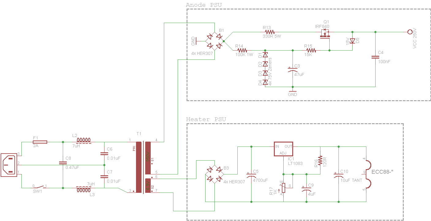
As you can notice, this PSU has an EMI filter circuit before the transformer. The transformer has 2 secondary windings – 250VAC and 7-12VAC. The anode supply is then filtered and regulated by a capacitor and an IRF840 mosfet. The voltage rises slowly to keep the tubes safe by charging C3 through R14 to a reference voltage created using 4x75V zener diodes(D1-D4) which makes the regulator output 243V after the ~7V dropout of the mosfet. The heater supply is a classic LT1083 regulator circuit. Output voltage must be adjusted to 6.3VDC via R17. If you have a transformer with a 6.3V secondary you can heat the tubes directly from the secondary winding dropping the heater supply part, but that can increase hum.
I use PCM2707 in a standard circuit for a USB to I2S converter, in order to add an USB input to the DAC. A post will follow with pictures and sound quality review when my DAC is completely ready.
Thank you for reading.