I was in need of a DAC which will be used as my main audio source. The requirements were simple:
– Digital inputs switching. I wanted to use the same DAC whether I am listening from my DIY Volumio streaming device or watching a movie/playing Xbox.
– Of course I also want the best sound quality.
After reading this article, the PCM1794 datasheet and talking to a friend of mine who works in a professional audio equipment manufacturing company I decided to try the PCM1794 from Burr Brown for this project. I did a quick search on Aliexpress for readily available PCBs based on PCM1794 and I came across one that looked well made. The PSU part is well separated utilising:
– Four separate transformer windings with 3 bridge rectifiers (MCU+LCD; digital section PSU; analog section PSU)
– Five on board regulators (LM7805 for the uC/LCD, LT1968-3.3V for the AK4118 and PCM1794 digital supply, LM317(5V) for the PCM1794 analog VCC, LM317/337(+-15V) for the opamp supply.
– Ground planes
The board costs only 47$ so I expected cheap capacitors and probably fake AD827 opamps. After 20 days I received the board. I was right, they used cheap caps(except the big filter Nichicons, which seem good) and the opamps are probably fake at this price so I started planning mods to the board.
The first thing I did was to test the board before doing anything so I know if it works as expected. I plugged in all required windings, plugged my set-top box as digital source with an optical cable and flipped the switch…
F*ck… The thing is not even working…
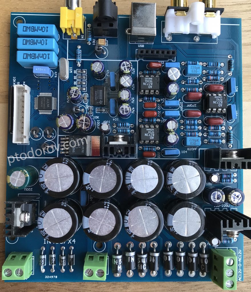
The first thing I did was to measure all the supplies. I found out that the LT1968-3.3 had 2.0V at its output so the AK4118/PCM1794 didn’t get enough voltage to work. I desoldered the LT1968 and soldered a LD1117V33. It finally worked. Good thing is I don’t have to return it to the seller and I can start with the mods.
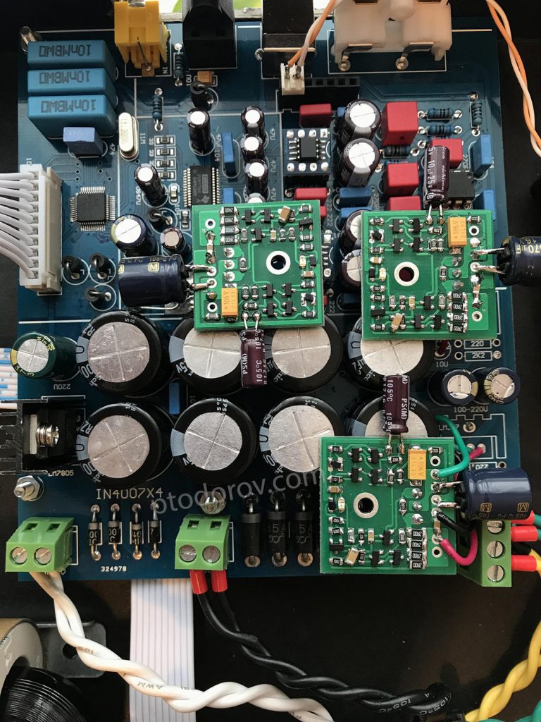
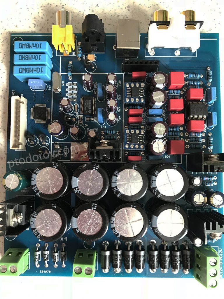
After inspecting the board and following some traces I have annotated the photo of the board of all planned mods for convenience.
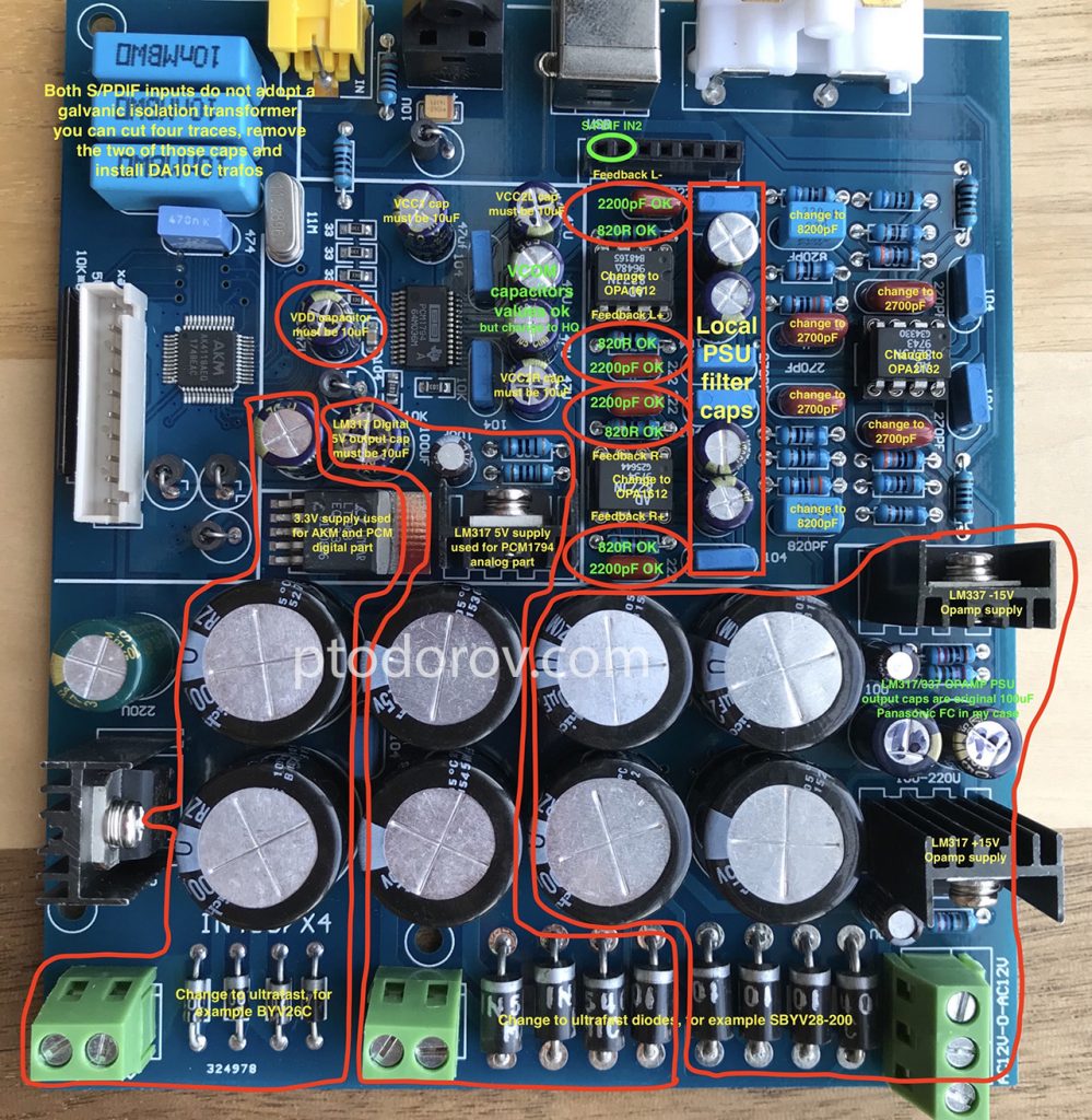
I have done the following modifications:
1. Change all big diodes in the rectifier bridge to SB5A0 fast recovery diodes because the old ones were standard Chinese diodes with shady letters on them.
2. I checked all resistor values according to the following OPA1611(single version of OPA1612) schematic and found out that the 8200pF capacitors were actually 220pF(marked on board as 820pF) and the 2700pF were actually 270pF(marked on board as 270pF). Resistor values were right according to this schematic.
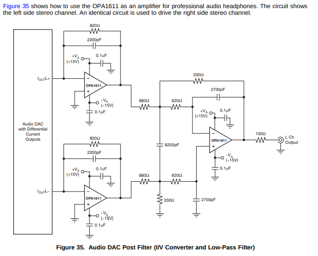
Changed those to Wima FKS2 capacitors with the right values and also changed the 2200pF metallized film capacitors in the feedback of the I/V stage with same value Wima FKS2.
3. Changed all electrolytic capacitors to Nichicon UPS which are low impedance, high temp range capacitors suitable for PSU usage. Some of the capacitors were 47uF instead of the 10uF according to the PCM1794 datasheet.
4. The final thing to do was change two of the AD827(probably fake) to two OPA1612 opamps in the I/V stage and change the third AD827 in the differential to single convertor stage to OPA2132.
I will now let the DAC burn in for a couple dozen hours and I will start listening!
15.01.2019 UPDATE:
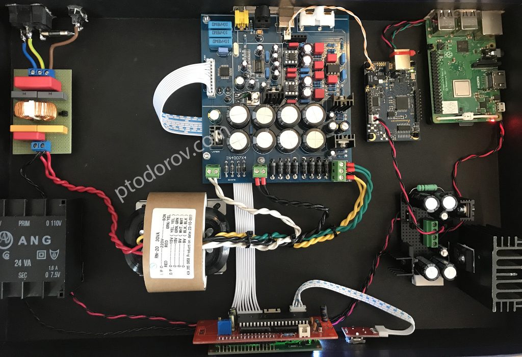
Below is a picture of the full setup in a temporary enclosure consisting of the following:
– A DIY AC filter
– 2x15VAC+2x9VAC R-Core transformer feeding the DAC board
– 2×7,5VAC feeding the XMOS reclock and Raspberry Pi
– Raspberry Pi 3 running Volumio fed by a LT1083 + CRC filter PSU(on the black prototype PCB)
– JLSounds XMOS, with it’s reclock fed by an LM317 + CRC PSU(also on the black board)
– The modified chinese PCM1794 board
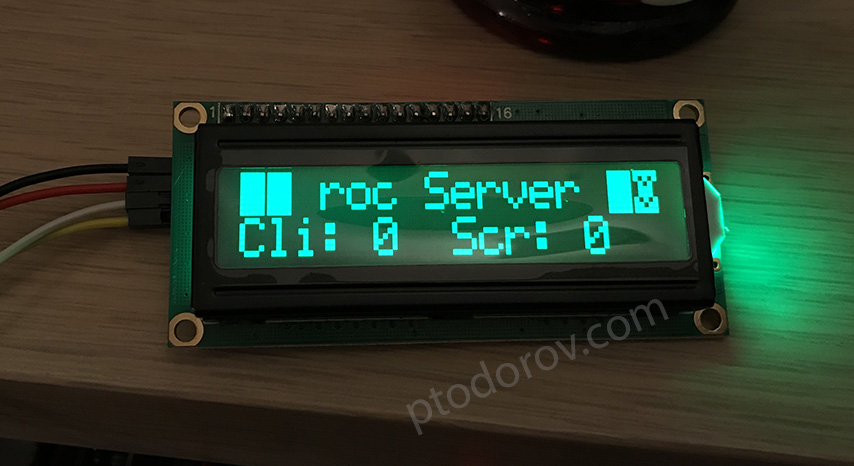
– An LCD display+MCU+rotary switch that came with the Chinese board used to switch digital inputs and display current signal frequency, considering to remove that and put a white on black OLED connected to the Raspberry to display current song, bitrate, res etc.
While still burning in, the sound of the PCM1794 is amazing. TBH I have never expected such a detailed sound that is still warm and pleasant to listen to from a delta-sigma DAC except for the most expensive Sabre pros. I don’t believe the TDA1541 myths anymore.
The good thing is that the whole streamer/DAC costed less than 250$ including the trafos, raspberry, xmos, memory card, DAC board and all the components for the upgrade. It allows me to listen to music from online streaming services such as Spotify and Tidal, USB SSD and I can still switch to the toslink coming from my TV with one click and use the DAC for Xbox(pass-through) and Netflix.
I will make a full blog post about the whole streamer/DAC once I am done with lower noise discrete PSUs and the enclosure.
UPDATE 10.02.2019:
As a final update to the DAC board I decided to replace all the analog audio power supply LM317/337 regulators (opamp supplies and PCM1794 AVCC supply) with DIY discrete regulators with very high Power Supply Rejection Ratio and very low outpud impedance in the audio spectrum. The schematic is designed by a friend from our local audiophile forum (Thanks, Sandy!). Some measurements of the discrete regulator:
The red line is the noise of the discrete regulator, the blue line is the self noise of the measurement setup. WARNING: The numbers are offset by 100dB because of the measurement setup, so -30db must be read as -130dB:
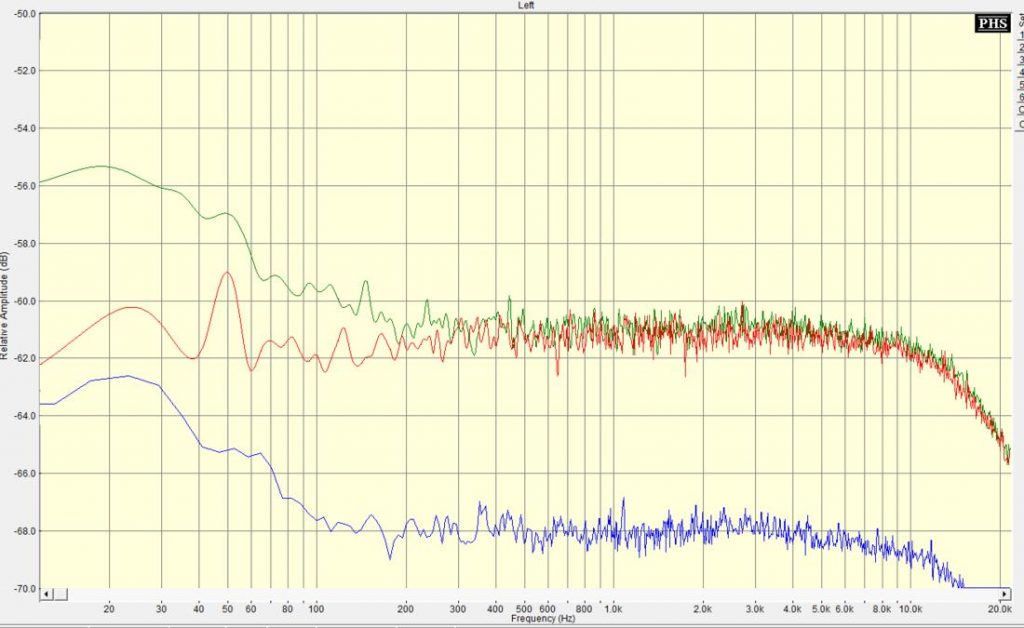
So the PSRR of the discrete regulator is ~ -125dB.
For comparison, measurements of the previous regulators (LM317). WARNING: The numbers are offset by 60dB because of the measurement setup, so -20db must be read as -80dB:
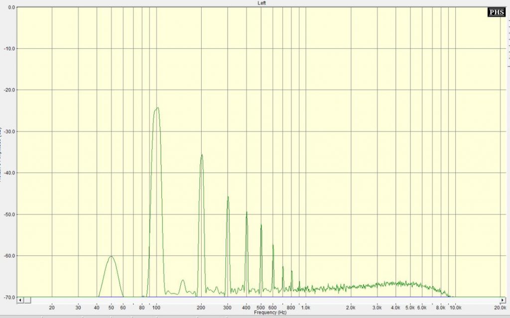
LM317 measured PSRR: ~ -83dB
Also, the discrete regulator has a lot better reaction to load impulses compared to the LM317/337.
I hate soldering SMD to such tiny boards with my not so good soldering iron but the end result is worth it. A photo with the all three discrete regulators soldered and fit to the board:
