Tag: amplifier

17
Aug

A solid-state tale. Slone’s Figure 6.21 or micro-ZUS (uZUS)

After finishing my last solid-state amplifier I was away from the DIY audio scene for some months but a few weeks ago something bad happened to my last amp. My roommate was helping my move my audio components from my car trunk to my apartment and he accidentally dropped my solid state amplifier down the stairs. The amplifier didn’t have an enclosure and all the components were mounted on a wooden board so you can imagine what happened to the PCBs after that accident. It was time for a new build! After browsing the Bgaudioclub forum I came across a great thread about the Randy Slone’s favourite amplifier schematic from his book The Audiophile’s Project Sourcebook. I don’t know if it’s ok to post the schematics here, but if I infringed any copyrights please drop me a mail to remove it.

Randy Slone Figure 6.21 Schematic

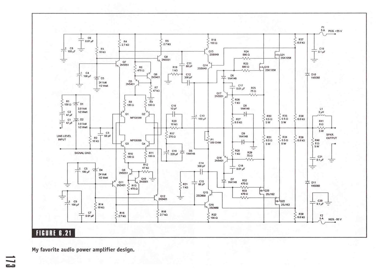
As the schematic is relatively complex for a homemade PCB. I found out that a forum mate had some PCBs left and I bought two. Then I ordered the parts required for this build from Comet/Farnell. The problem was they didn’t have the 2SK1058 and 2SJ162, so I ordered them directly from the USA to be sure that I won’t come across fake transistors. A few days later I had everything to begin with the build.

Randy Slone Figure 6.21 PCB

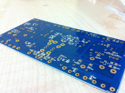
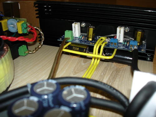
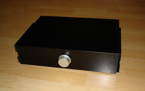
Almost all the components on the PCB were SMD including many transistors and I don’t have a reflow station so it took a some hours to solder everything on both sides of the PCBs. After I soldered everything, mounted the transistors to a heatsink and connected the cables I plugged the amplifier into the mains. Hm, there wasn’t anything coming out from the speakers… I wondered what’s wrong, but then I pressed play. The amplifier was perfectly working, it was so quiet that I could not hear any noise coming from my speakers… NICE!

Randy Slone Figure 6.21 Done

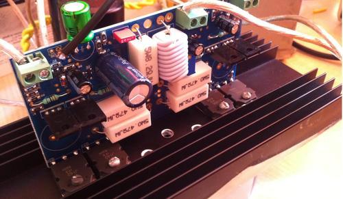
There are silicone insulation pads between the transistors and the heatsink, I just cut them to match the size of the transistors and therefore you can’t see them.
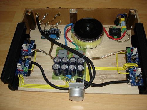
The PSU:

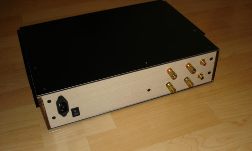
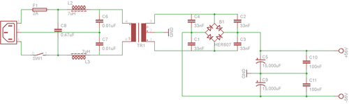
It is a classic unregulated PSU consisting of a 500VA copper shield insulated transformer with a 39-0-39VAC secondary, 4x HER607 diodes shunted with 4x 33nF caps and 2x 15,000uF/63V filter capacitors(+100nF MKPs). An EMI filter is added before the trans.

Randy Slone Figure 6.21 PSU Schematic

First impression:

My first impression of this amplifier was “WOW”… As soon as I pressed play the room was filled with warm yet very dynamic sound with plenty of bass considering my bookshelf speakers /B&W 685/. I listened to the following tracks at first: Sade – Jezebel, Sade – No Ordinary Love, Candy Dulfer – Lilly Was Here, AYO – Without You, Zazz – Je Veux, Steve Strauss – Mr. Bones and some orchestra.  I knew that the 22uF bipolar Nichicon Muse at the input was not the best choice for this amplifier/for any amplifier/ but I still liked the sound. After an hour or so listening, the capacitor started to settle down and the sound became more transparent and colorful. I didn’t have enough time to let the amplifier settle down and listen to it because I went on a vacation for a few days. I will post a follow-up with more details about the build and the sound when I get back in a few days.

So far this is the best DIY solid-state amplifier I’ve ever heard!

15
Aug

My first tube amplifier (Part 1)

After discussing the schematics with members of Bgaudioclub I decided to build my first tube amplifier using the E180F and 6B4G vacuum tubes. I drew the schematic(thanks to 50AE) in Eagle and I will be starting to build this amplifier shortly. The costs will be more than in the solid state amplifiers I have built so far, therefore I need to spare some cash first.

The schematic:

As you can see the schematic includes an EMI filter before the transformer and makes use of 5ц4м(5z4) as a full-wave vacuum tube rectifier. The transformer has secondary windings outputting 290-0-290VAC, 5VAC, 6.3VAC. The combination of D1,D2,RP2 and C10 is a “hum control” circuit I saw here as it is recommended for directly heated tubes with AC. There is nothing fancy in the other part of the schematic. I expect this amplifier to have a solid and balanced sound which is not too coloured as the state of the tubes matches their documentation, yet nice to listen to. I will keep you posted when I have any progress on this project. Feel free to comment the schematic! Thank you for reading.

14
Aug

Plamen’s LM3886 Gainclone

Concept:

As this was my first DIY amplifier I decided I need to create something easy to assemble yet good sounding. I started to plan the build. After some reading I decided to use the schematic posted by Alex Wong for 2x LM3886 per channel in parallel

A DC speaker protection circuit is added and therefore I needed another small transformer to power it. I also added and EMI filter before the transformers which greatly reduced the hum I can hear from the speakers.

PSU:

As this is not a top-notch sonic quality amplifier I decided not to spend a fortune on the PSU. I also think that this particular amplifier won’t sound much different with a regulated PS. I don’t have schematics for the PS, but it’s just a 400VA 2x25VAC toroidal transformer > 2x 20A rectifiers with each diode shunted with a 10nF cap > 8x 4700uF 50V Low-ESR caps. If you decide to build a Gainclone I can tell you that the filter capacitors in the PSU have tha largest impact on the sound characteristics of the amplifier so be sure to experiment a bit with their capacity/type. All AC cables are twisted to reduce noises. The yellow DC cables are made of 1.5mm2 solid core OFC.

Enclosure:

I really wanted a good and solid enclosure which still doesn’t look like most of the DIY amplifiers I see on the internet. I really liked the enclosures Alex Wong uses in his projects, especially BPA300, but I really didn’t feel like paying 100$ for an enclosure of a 100$ amplifier… So I decided to DIY a bit. The floor and the right side of the box are cut from leftovers of a laminate flooring from my apartment using a regular cutting saw table and then put together using little aluminium profille that I had lying around. The heatsinks are then screwed to the lower panel.

The upper/lower/front panel is made of a bent material called Etalbond but black or white plexiglass will look even better. As you can see the potentiometer is put on a L-shaped piece of aluminium bolted to the wood panel and it’s shaft goes through a hole in the front side of the Etalbond/Plexiglass panel.

Conclusion:

I had a great fun building this amplifier and I recommend it to beginner/intermediate users of the DIY audio scene. It sounds good, especially with a tube preamplifier. I’m sure you don’t expect that sound from a chipamp, but LM3886 and LM1875 are really good. I gave this amplifier to my brother as a present because I am planning to build my next solid-state amplifier in the next few days. Thank you for reading, now grab the soldering iron and do something cool!