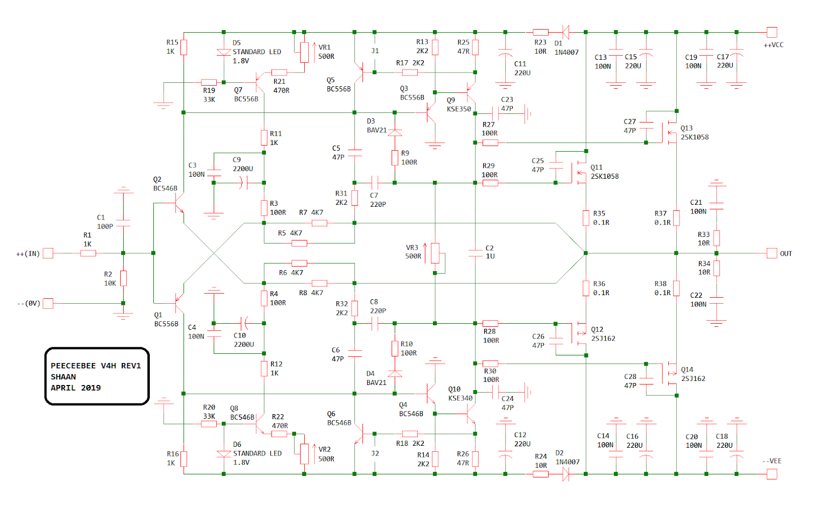
While I was browsing the DIYAudio.com forum I found a popular schematic called PeeCeeBee V4. It had a lot of positive reviews from the DIYaudio members who had already assembled it and it looked simple and easy to assemble for someone with not so much knowledge in the solid state amplifiers.
The author (Shaan) created and published a more powerful version of it called PeeCeeBee V4H which was able to push 150W into 8ohm load on +/-56V PSU, just about the right power to satisfy my somehow low sensitivity ATC SCM11 (v2/curved) speakers.
Gathering the parts
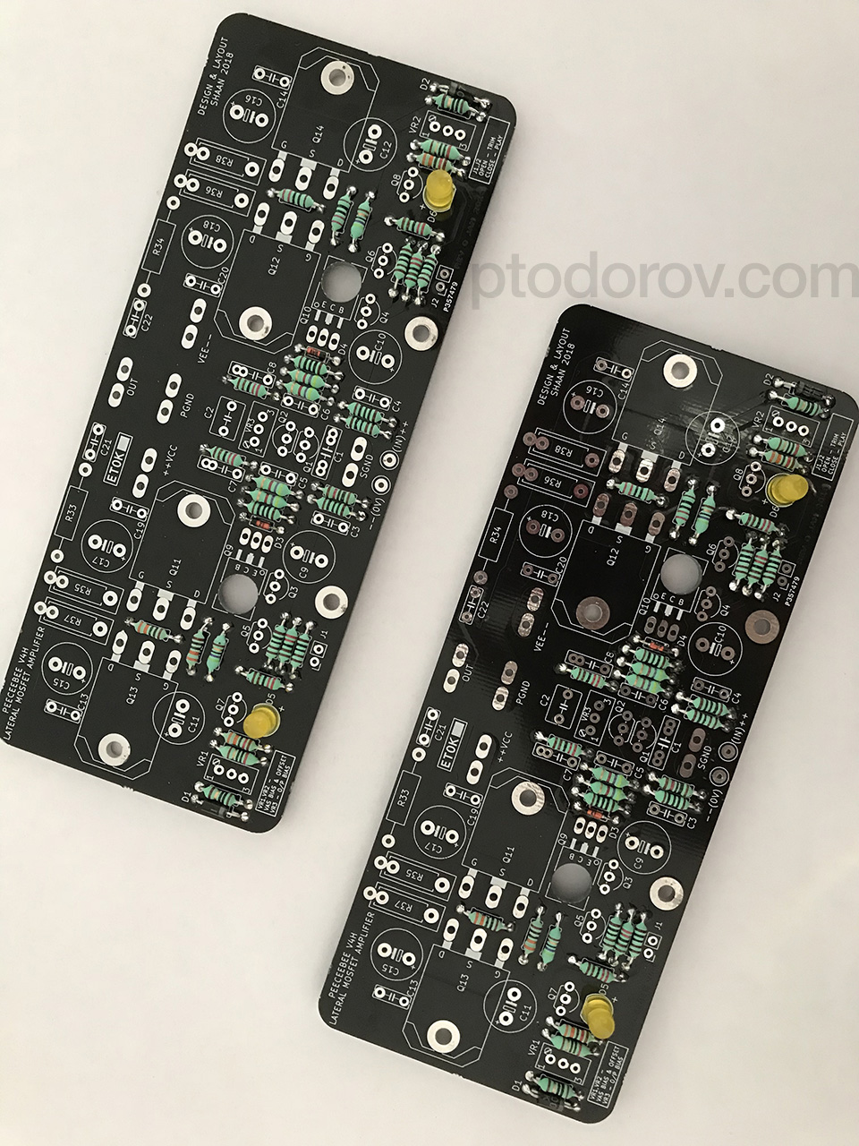
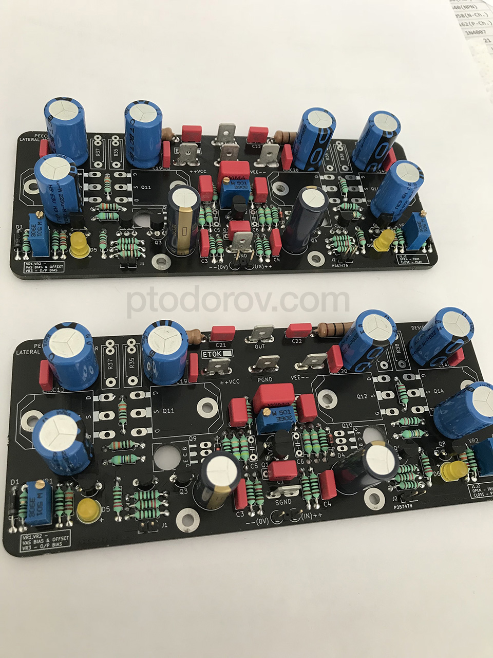
I ordered PCBs from the author himself including genuine pairs of 2SK1058/2SJ162 needed for 2 channels which he shipped to me in Bulgaria. Shaan’s PCBs are of extremely good quality and visual appearance.
While I was waiting for the delivery I called Novatech Ltd to order a custom winded 40-0-40VAC @ ~550W toroid.
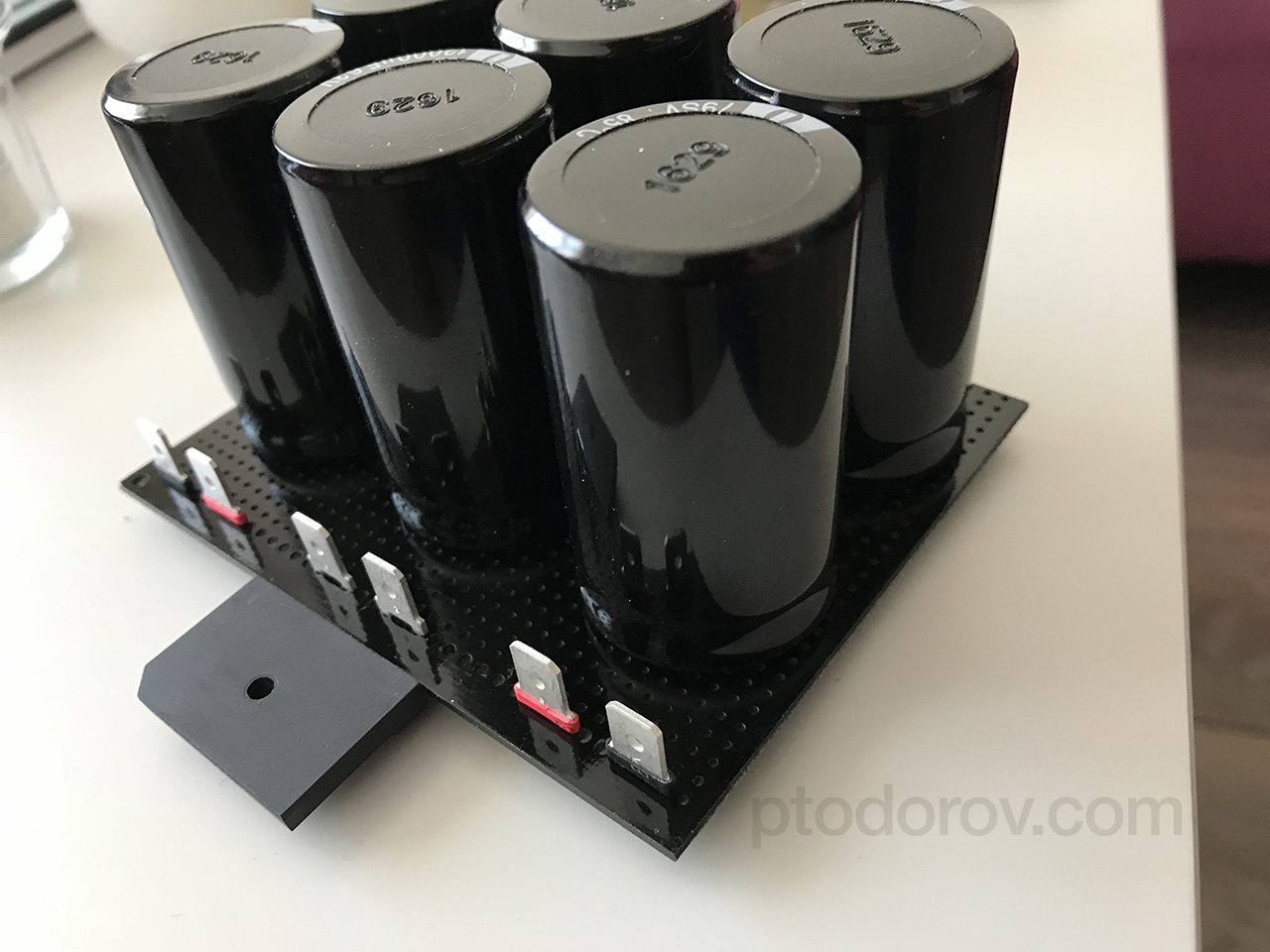
For the PSU I chose to use six Cornell Dubilier(CDE) SLPX 12,000uF 63V for a total of 72,000uF or 36,000uF per rail because they seem like the best bang for the buck. I bought all the capacitors used in the PSU and amplifier boards at from Stefan at Stesys.eu. All capacitors are genuine, the prices are the lowest I could find and they deliver all over the world. All other passives needed for the amplifier I have bought from Comet.bg and Farnell. All resistors are 1% or better, all small capacitors are Wima.
Assembling the boards
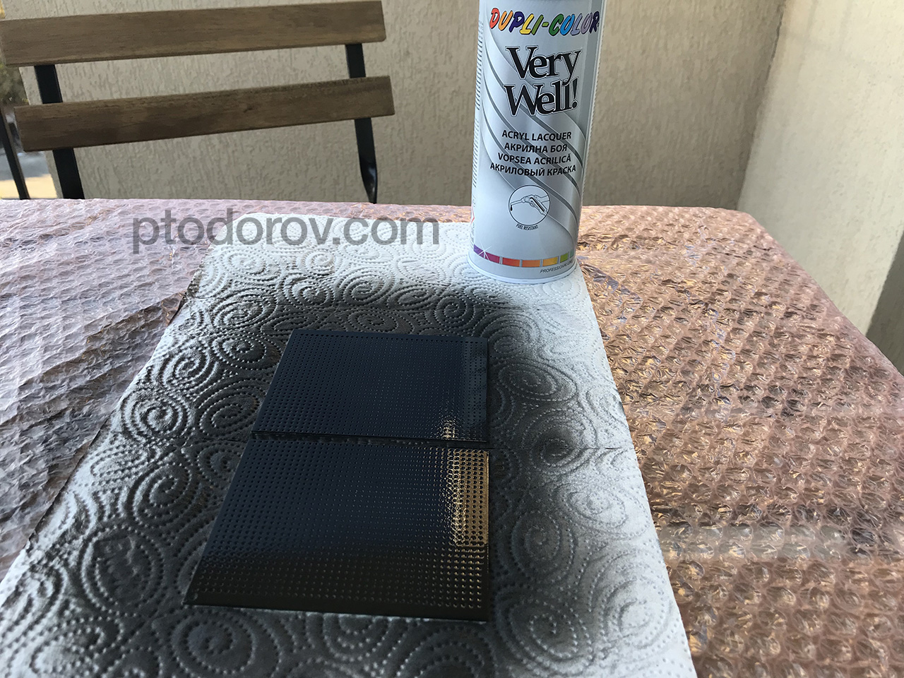
I decided not to waste time ordering a custom PCB but rather paint a universal PCB with black spray paint as the other PCBs are also black. Assembling the PSU board was pretty quick, it consists of a bridge rectifier, 6x 12,000uF capacitors and some snubbers.
For the assembly of the amplifier boards the author of the schematic/PCBs provides a great instructions and there is nothing more than I can add to it to make it easier.
Here are some photos from the assembly of the amplifier boards.
The hardest thing of all the V4H assembly for me was drilling the aluminium heatsinks and tapping the holes. I have used a 2,5mm drill to make the holes and a M3 tap to make the thread. Make sure to take your time and use alcohol while drilling and tapping instead of oil. Alcohol is better for aluminium. It is nearly impossible not to break a drill or a tap when using a hand drill machine instead of a drill machine with a stand or a table drill machine. Breaking a drill or tap inside the aluminium heatsink is a very bad experience because there is no way to get it out of there without destoying the hole/thread.
Warning: REALLY, TAKE YOUR TIME WHEN DRILLING AND TAPPING! If you ruin even one hole/thread you need to redrill all other holes because the transistors are in exact positions from one another.
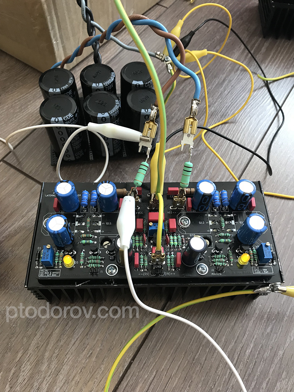
The last picture was with resistors needed for the setup process consisting of VAS (Voltage Amplifier Stage) biasing, offset trimming and mosfet biasing. The process is very well explained in Shaan’s instructions.
First listening tests
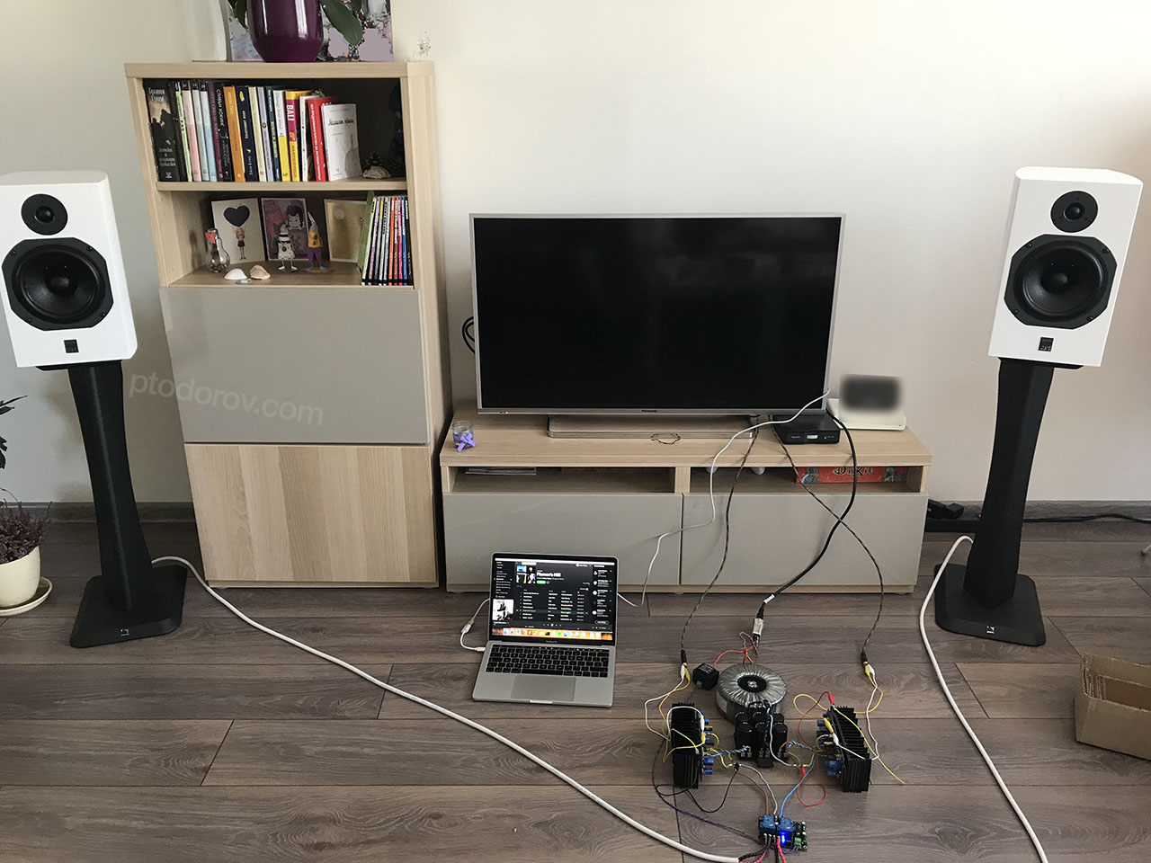
After a few days of settling my first impressions are that the sound is very natural and pleasant to the ears. Overall I am completely satisfied with it. I will write a more detailed review of the sound once I have something good enough to compare to in the same room/setup.
My current setup is:
Source: DIY Volumio > XMOS > PCM1794 Source
Interconnects: DIY OFC Silver Plated Interconnects
Amplifier: DIY PeeCeeBee V4H Amplifier
Speaker cable: Chord Odyssey 2
Speakers: ATC SCM 11 v2(Curved)
I will update the post with the final look of the amplifier once I finish the enclosure.
Links for PCB info/order:
https://www.diyaudio.com/forums/group-buys/317151-peeceebee-v4h-gb.html
https://www.facebook.com/shaanpeeceebee/