Category: Solid State

15
Jan

First shot at class D with Hypex

After making more than 5 different DIY amplifiers in class AB I decided to try class D. After spending some time reading threads in diyaudio, audiosciencereview and asking in our local forum about what are the best class D modules I had to choose between Purifi, Hypex UcG, Hypex Ncore, ICEPower and a few others. Purifi 1ET400 has the best specs according to the datasheet but it is priced at around 600EUR for stereo set even without a SMPS. I didn’t feel like spending 900-1000EUR for a DIY amplifier just to hear what class D has to offer. There is a chance I won’t like class D sound at all. Seems that Hypex Ncore is a middle ground in high end class D modules, placed somewhere between Hypex UcG and Purifi according to several forum members.

I was initially aiming at NC252MP which is 2x250W@4R and MP means that it has integrated SMPS on the same board. Class D is all about high efficiency so why not spend a few more bucks and go for the NC502MP instead? It is rated at 2x500W at 4R and 2x350W at 8R which seems like a good match for my low sensitivity ATC speakers. I found a brand new NC502MP online so I ordered it. Keep in mind that you can’t buy NC252/502 from Hypex directly because they are OEM only, you can only buy NC400 and UcG series from their website diyclassd as a non-OEM customer. However, from time to time NC252/502MP boards appear on ebay so just look there.

The measurements of the amplifier look very promising, especially the THD. THD+N vs power plot for NC502MP:
THD+N vs power Hypex NC502MP

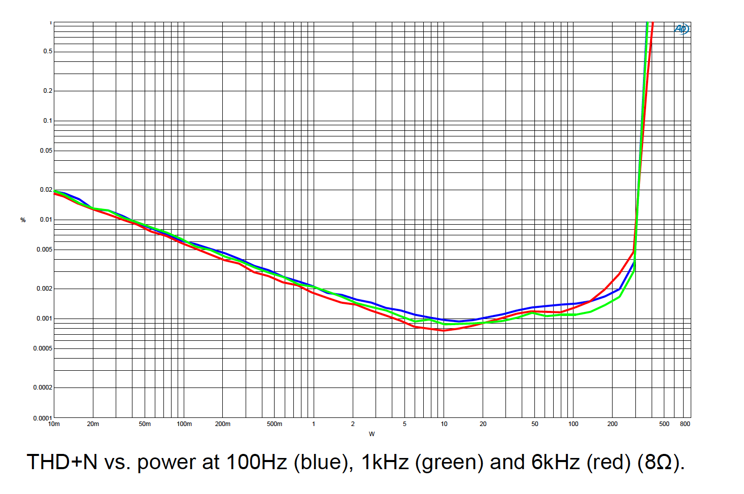
Here is the full datasheet of Hypex NC502MP.

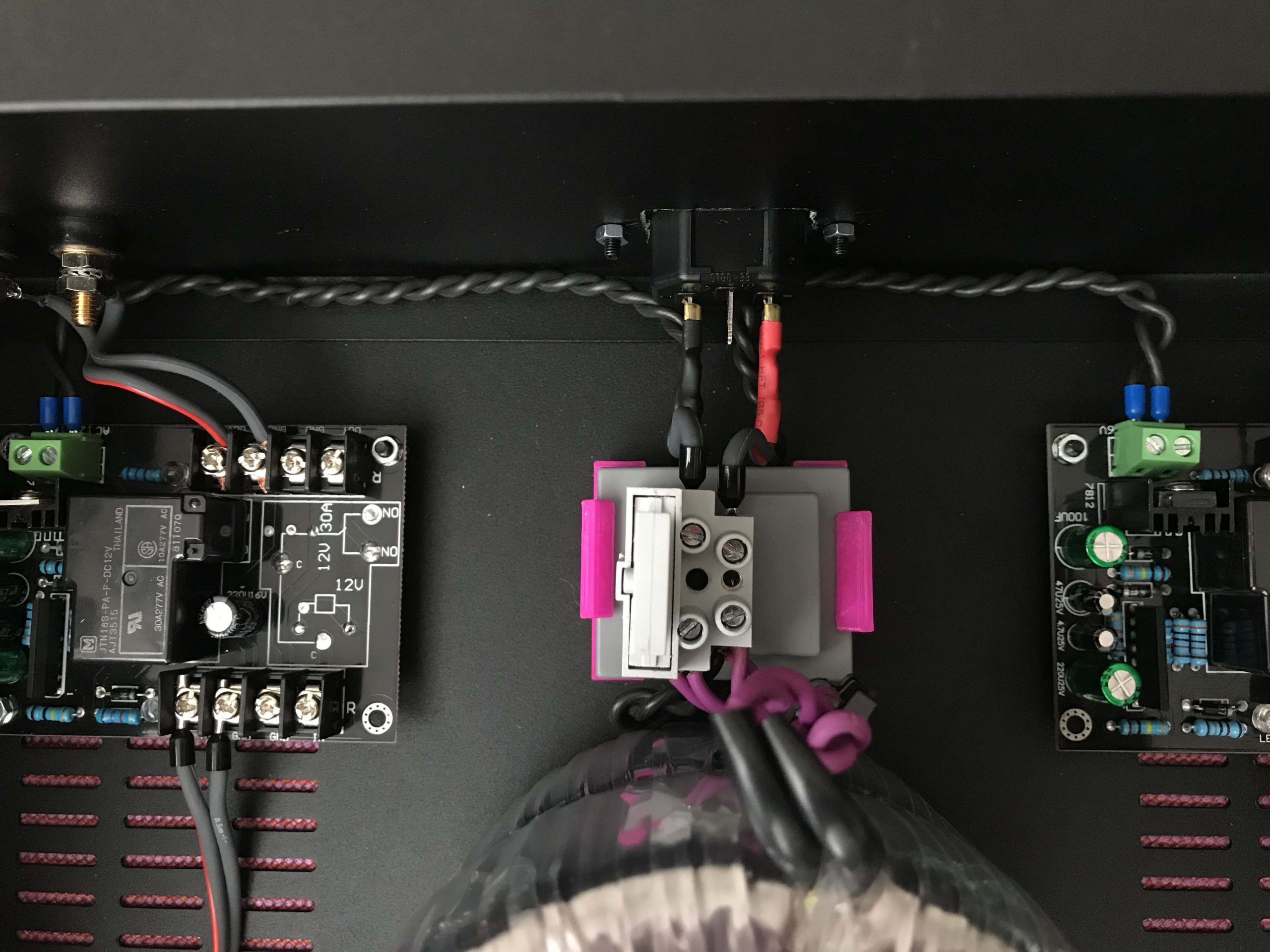
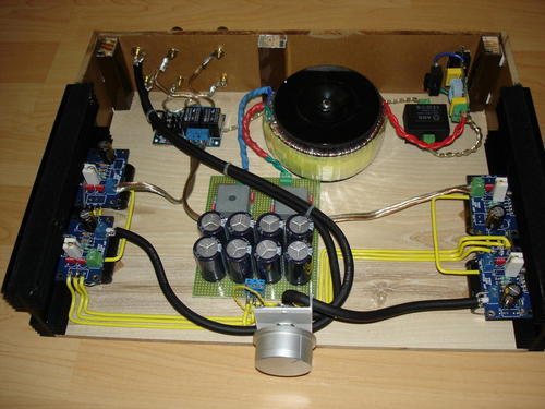
While waiting for it to be shipped I designed a small “interface” board to fit the balanced(XLR) and single ended(RCA) inputs, relays to switch between them and also route some connections to allow for an external board to monitor and control the Hypex amplifier. I will probably use an Arduino based board which will monitor clipping indicator, temperature and current sense which are all available on the NC502MP 16pin connector.

Hypex Ncore input board

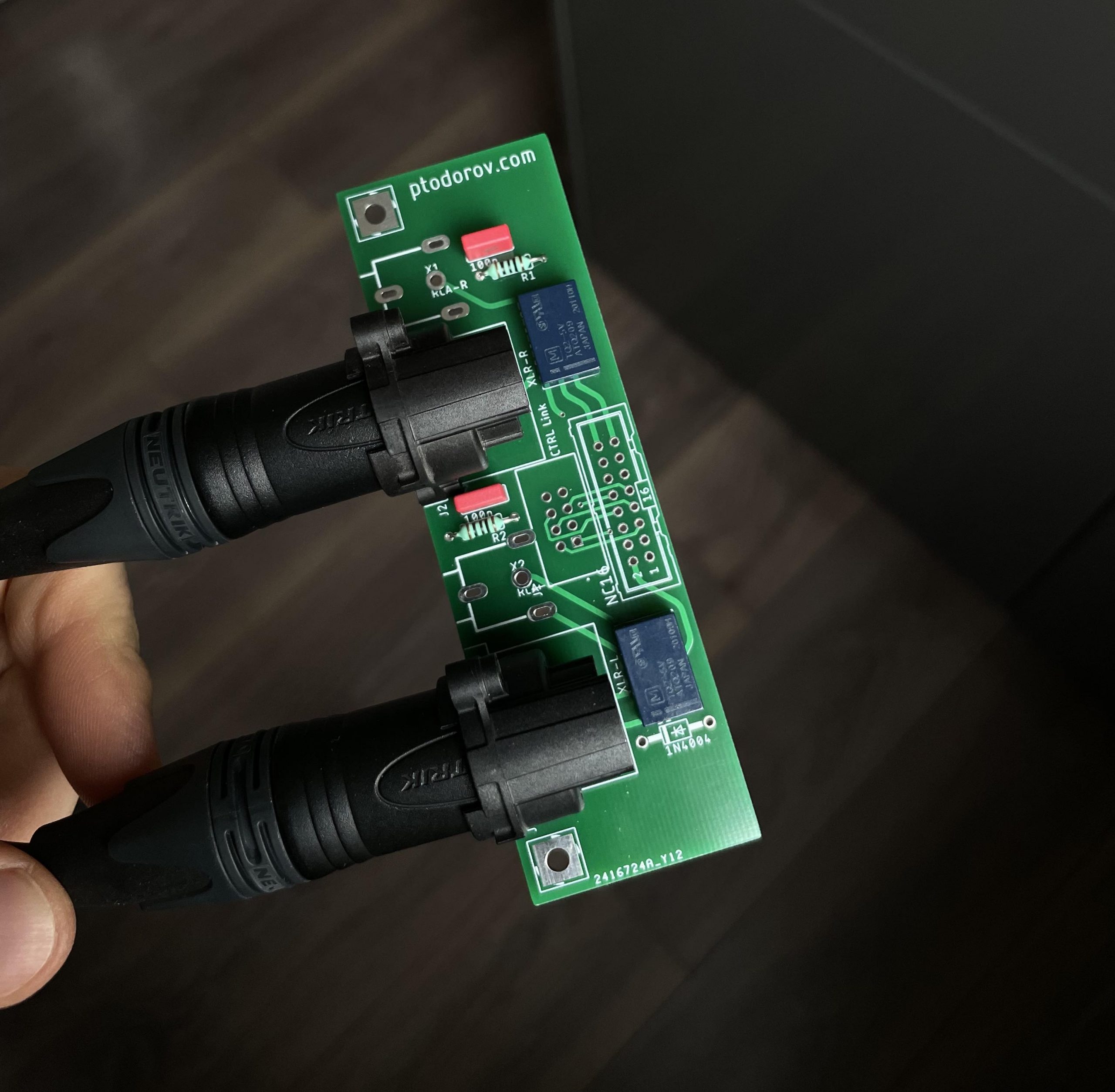
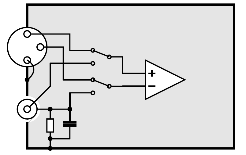
It hosts 2x Neutrik NC3-FAH0 XLR connectors, two RCA connectors (also Neutrik) and 100nF/100R RC network for the single ended inputs as recommended by Hypex in their great XLR pin1 grounding guide which relates to every amplifier with an XLR input too.

SE/balanced input selector

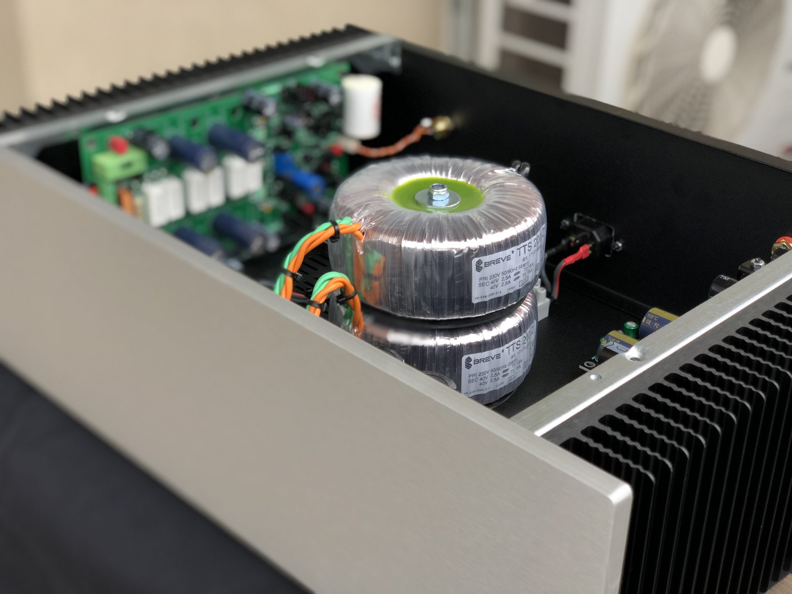
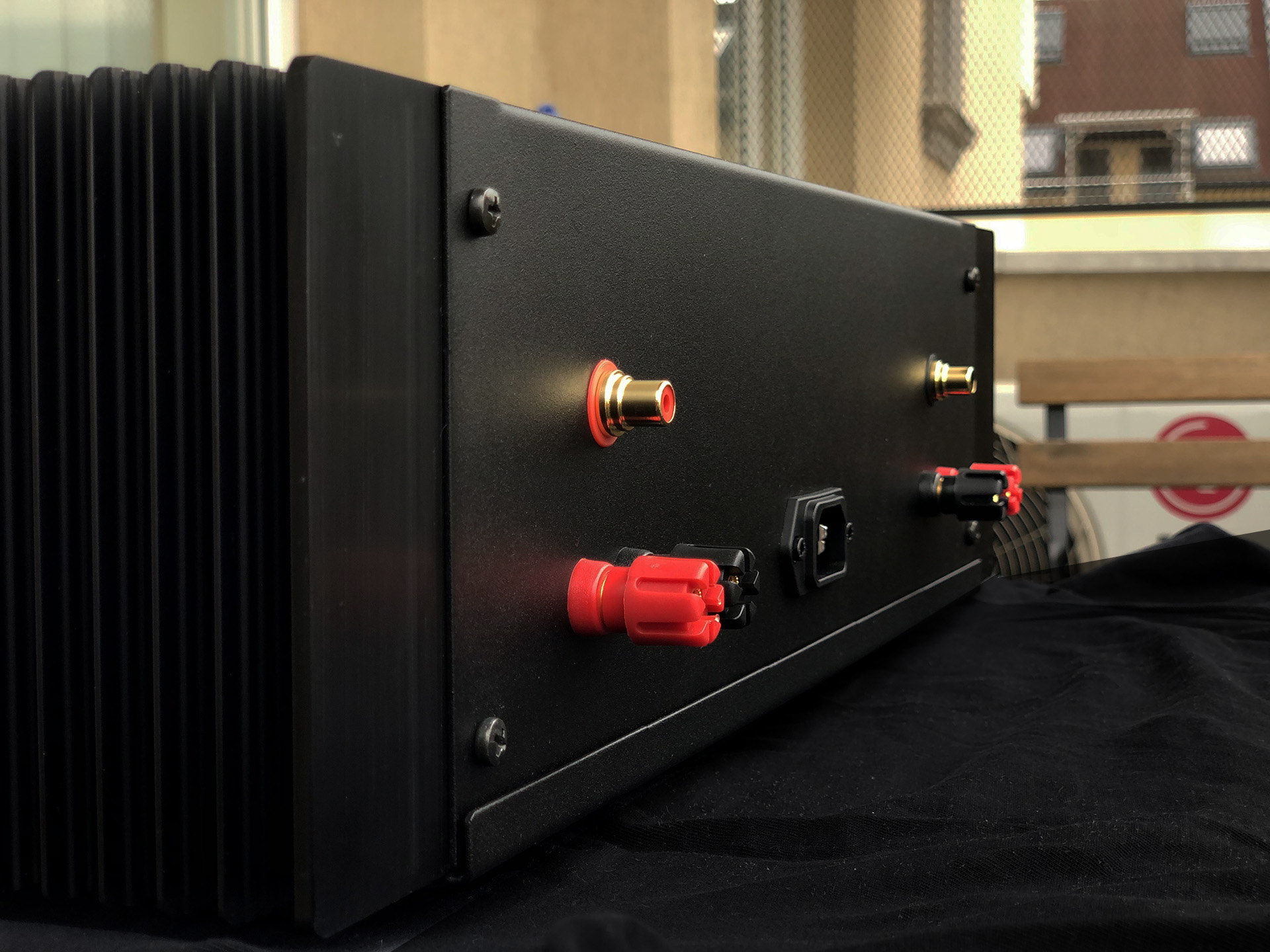
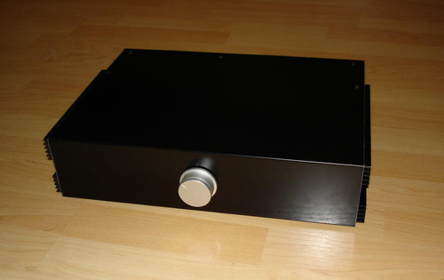
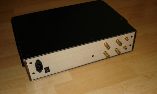
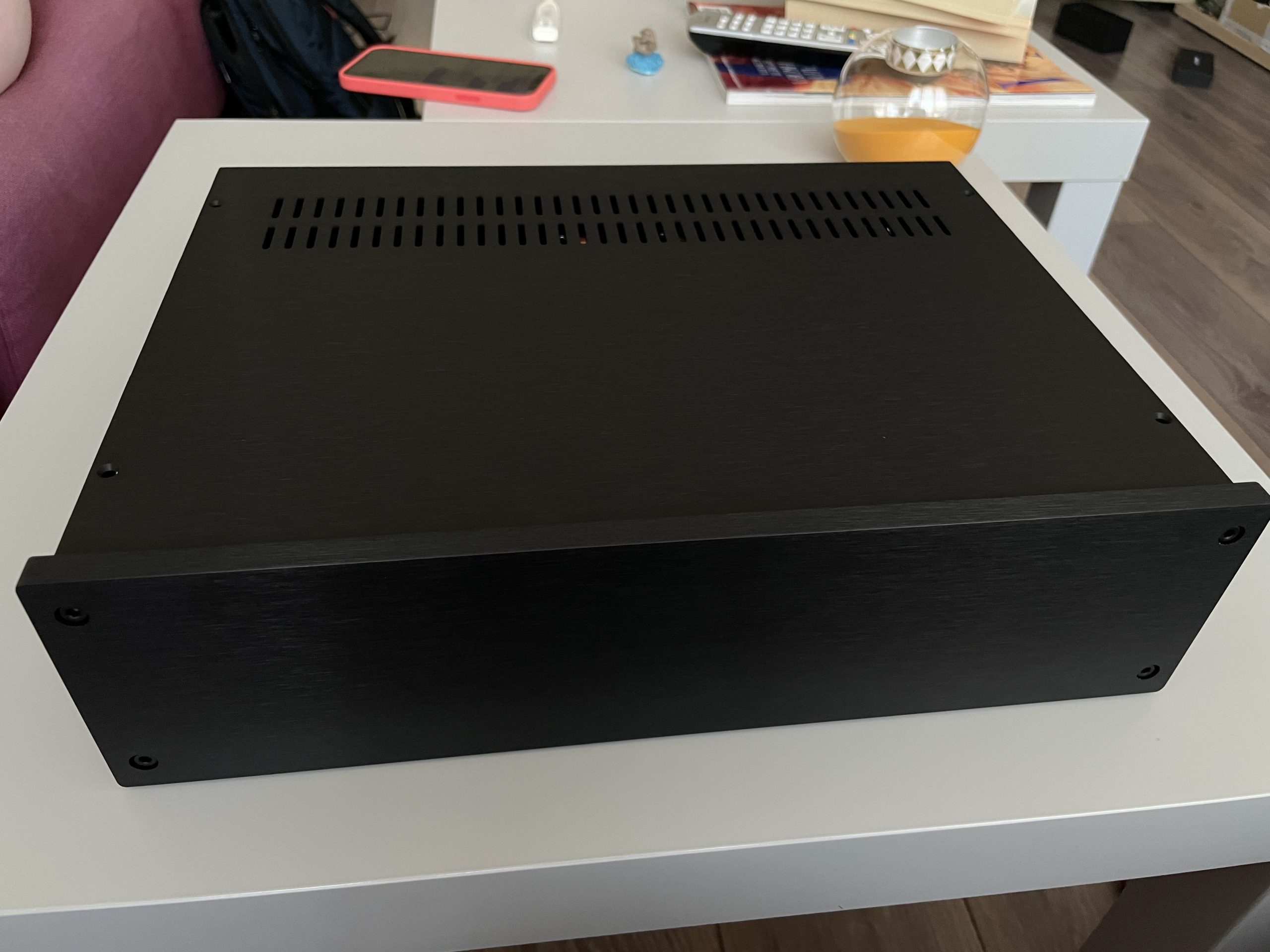
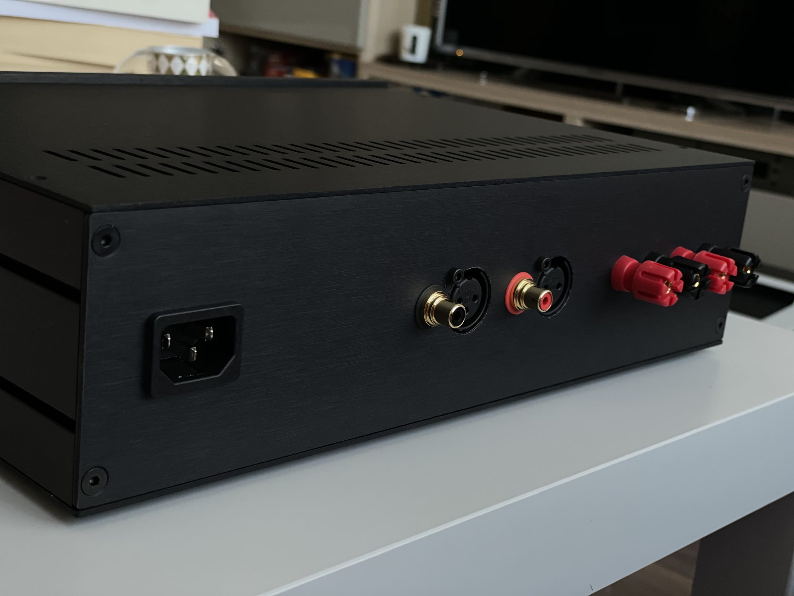
The enclosure of choice is once again from my friend Gianluca at Modushop(HiFi2000). They sent me a black front panel instead of the silver ones I use for my other amplifiers but I didn’t even bother to return it because I love how it looks.

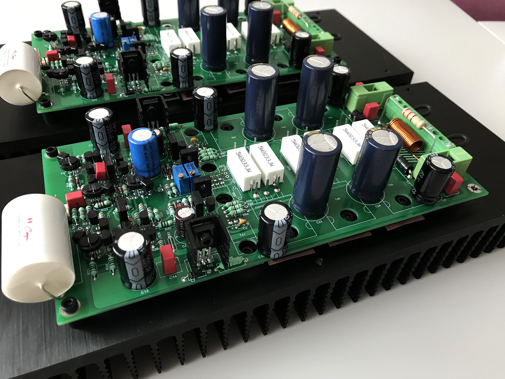
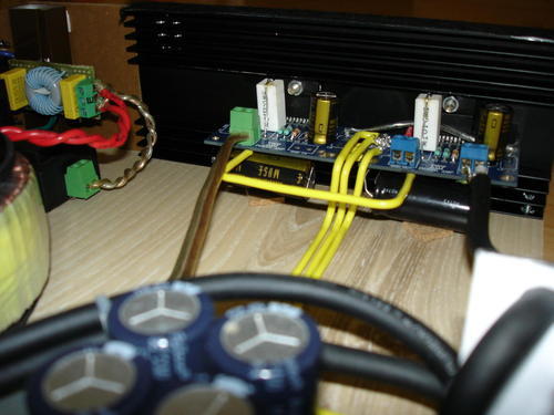
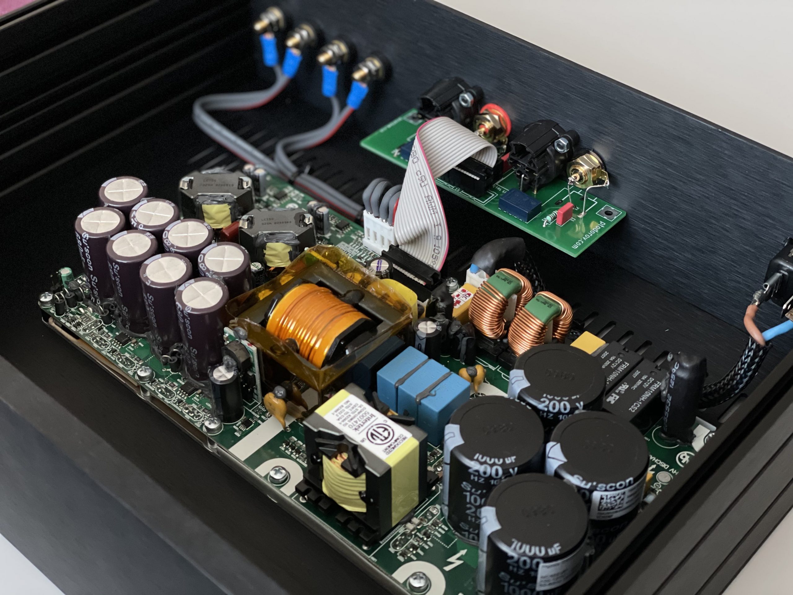
Here are some photos of how it turned out. I still have to figure out the control board but the amplifier works without it with the inputs defaulted to XLR because that’s what I connected to normally closed contacts of the relay.

DIY Hypex NC502MP amplifier front
DIY Hypex NC502MP amplifier rear
DIY Hypex NC502MP amplifier inside

I still have to let it run for at least 20 hours before sharing my opinion on how it sounds compared to my best sounding class AB amplifier.

Once I’m ready with the control board I will update this post.

11
Jan

DIY Class AB Amplifier – Apex A40

After listening to the PeeCeeBee V4H for a while I decided it is time to finally blow the dust out of my soldering iron and take a new challenge. In our local DIY audio forum an interesting schematic started a very enthusiastic discussion and a few members swore that it sounded amazing. The schematic was called “A40” and it was created by Mile Slavković (Apex Audio), a neighbour from Serbia. Our community members did modify it a little and my friend Hristo Elefterov created a really good PCB design for it because the one that was kindly shared on DIYAudio had some design flaws especially with grounding. Here is the modified schematic and PCB design:

Apex A40 Schematic
Apex A40 PCB 3D
Thanks Hristo for the work. Please drop me an email if you like to get the PCBs.

I decided to build it in dual mono configuration, that’s basically two completely separated units for each channel in one enclosure.

Transformers of choice are two great looking Breve Tufvassons 200VA 2x40VAC toroidals from TME, one for each channel. PSU boards are very trivial thus I didn’t take any close up photos of them. Each channel is supplied by a DIY PCB which consists of a 25A bridge rectifier and four 12,000uF Cornell Dubilier SLPX, two for each supply rail. Total of 96,000uF for both channels.

Another small 6VA transformer is used for the speaker protection boards and is bolted to the enclosure using a custom drawn and 3D printed stand. I love how my 3D printer allows me to make such things in less than an hour. Speaker protection boards are from Aliexpress but I did modify them. I am using two stereo boards which I have converted to mono to stick to my dual mono concept by removing one relay from each one and also upgraded the relays to high quality Panasonic relays.
Transformer for speaker protection boards, IEC inlet, fuse holder

All wiring is 4connect oxygen free copper 2×1.5mm2 and 2×2.5mm2. Input RCA jacks are Neutrik NYS367. Output terminals are Cliff TP/6. Output terminals are one of the hardest things to find nowadays. Always use good quality RCAs and output terminals in your amplifiers. Don’t buy the ones sold on Aliexpress if you don’t like your precious music distorted by a terrible choice of metal.

NB: I am not kidding. A friend was trying out to figure out a high THD of an amplifier and tried almost everything but it was still measuring bad. After a few days of experiments he found out that the conductance of the metal of the output terminals was so bad it affected the THD measurements negatively.

Bias is set at around 120mA per pair or 60mA each.

Here are a few photos from the finished amplifier:
Apex A40 boards
Apex A40 inside
Apex A40 top view
Apex A40 rear panel

Conclusion: I am not good at recreating my listening experience in words but I must say the modified Apex A40 schematic built properly in dual mono configuration raises the bar of DIY class AB amplifiers very high. +-56VDC supplies gets me 156W at 8R which is just enough to make my low sensitivity ATC speakers sound amazing.

14
May

My take on the PeeCeeBee V4H amplifier

While I was browsing the DIYAudio.com forum I found a popular schematic called PeeCeeBee V4. It had a lot of positive reviews from the DIYaudio members who had already assembled it and it looked simple and easy to assemble for someone with not so much knowledge in the solid state amplifiers.

The author (Shaan) created and published a more powerful version of it called PeeCeeBee V4H which was able to push 150W into 8ohm load on +/-56V PSU, just about the right power to satisfy my somehow low sensitivity ATC SCM11 (v2/curved) speakers.

PeeCeeBee V4H schematics

Gathering the parts

I ordered PCBs from the author himself including genuine pairs of 2SK1058/2SJ162 needed for 2 channels which he shipped to me in Bulgaria. Shaan’s PCBs are of extremely good quality and visual appearance.

While I was waiting for the delivery I called Novatech Ltd to order a custom winded 40-0-40VAC @ ~550W toroid.

For the PSU I chose to use six Cornell Dubilier(CDE) SLPX 12,000uF 63V for a total of 72,000uF or 36,000uF per rail because they seem like the best bang for the buck. I bought all the capacitors used in the PSU and amplifier boards at from Stefan at Stesys.eu. All capacitors are genuine, the prices are the lowest I could find and they deliver all over the world. All other passives needed for the amplifier I have bought from Comet.bg and Farnell. All resistors are 1% or better, all small capacitors are Wima.

Assembling the boards

I decided not to waste time ordering a custom PCB but rather paint a universal PCB with black spray paint as the other PCBs are also black. Assembling the PSU board was pretty quick, it consists of a bridge rectifier, 6x 12,000uF capacitors and some snubbers.
PeeCeeBee V4H PSU painted

PeeCeeBee V4H PSU done

For the assembly of the amplifier boards the author of the schematic/PCBs provides a great instructions and there is nothing more than I can add to it to make it easier.

Here are some photos from the assembly of the amplifier boards.
PeeCeeBee V4H Assembly Step 1

PeeCeeBee V4H Assembly Step 2

The hardest thing of all the V4H assembly for me was drilling the aluminium heatsinks and tapping the holes. I have used a 2,5mm drill to make the holes and a M3 tap to make the thread. Make sure to take your time and use alcohol while drilling and tapping instead of oil. Alcohol is better for aluminium. It is nearly impossible not to break a drill or a tap when using a hand drill machine instead of a drill machine with a stand or a table drill machine. Breaking a drill or tap inside the aluminium heatsink is a very bad experience because there is no way to get it out of there without destoying the hole/thread.

Warning: REALLY, TAKE YOUR TIME WHEN DRILLING AND TAPPING! If you ruin even one hole/thread you need to redrill all other holes because the transistors are in exact positions from one another.

PeeCeeBee V4H Assembly Step 3

The last picture was with resistors needed for the setup process consisting of VAS (Voltage Amplifier Stage) biasing, offset trimming and mosfet biasing. The process is very well explained in Shaan’s instructions.

First listening tests

PeeCeeBee V4H Test Run

After a few days of settling my first impressions are that the sound is very natural and pleasant to the ears. Overall I am completely satisfied with it. I will write a more detailed review of the sound once I have something good enough to compare to in the same room/setup.

My current setup is:
Source: DIY Volumio > XMOS > PCM1794 Source
Interconnects: DIY OFC Silver Plated Interconnects
Amplifier: DIY PeeCeeBee V4H Amplifier
Speaker cable: Chord Odyssey 2
Speakers: ATC SCM 11 v2(Curved)

I will update the post with the final look of the amplifier once I finish the enclosure.

Links for PCB info/order:
https://www.diyaudio.com/forums/group-buys/317151-peeceebee-v4h-gb.html
https://www.facebook.com/shaanpeeceebee/

17
Aug

A solid-state tale. Slone’s Figure 6.21 or micro-ZUS (uZUS)

After finishing my last solid-state amplifier I was away from the DIY audio scene for some months but a few weeks ago something bad happened to my last amp. My roommate was helping my move my audio components from my car trunk to my apartment and he accidentally dropped my solid state amplifier down the stairs. The amplifier didn’t have an enclosure and all the components were mounted on a wooden board so you can imagine what happened to the PCBs after that accident. It was time for a new build! After browsing the Bgaudioclub forum I came across a great thread about the Randy Slone’s favourite amplifier schematic from his book The Audiophile’s Project Sourcebook. I don’t know if it’s ok to post the schematics here, but if I infringed any copyrights please drop me a mail to remove it.

Randy Slone Figure 6.21 Schematic

As the schematic is relatively complex for a homemade PCB. I found out that a forum mate had some PCBs left and I bought two. Then I ordered the parts required for this build from Comet/Farnell. The problem was they didn’t have the 2SK1058 and 2SJ162, so I ordered them directly from the USA to be sure that I won’t come across fake transistors. A few days later I had everything to begin with the build.

Randy Slone Figure 6.21 PCB

Almost all the components on the PCB were SMD including many transistors and I don’t have a reflow station so it took a some hours to solder everything on both sides of the PCBs. After I soldered everything, mounted the transistors to a heatsink and connected the cables I plugged the amplifier into the mains. Hm, there wasn’t anything coming out from the speakers… I wondered what’s wrong, but then I pressed play. The amplifier was perfectly working, it was so quiet that I could not hear any noise coming from my speakers… NICE!

Randy Slone Figure 6.21 Done

There are silicone insulation pads between the transistors and the heatsink, I just cut them to match the size of the transistors and therefore you can’t see them.

The PSU:

It is a classic unregulated PSU consisting of a 500VA copper shield insulated transformer with a 39-0-39VAC secondary, 4x HER607 diodes shunted with 4x 33nF caps and 2x 15,000uF/63V filter capacitors(+100nF MKPs). An EMI filter is added before the trans.

Randy Slone Figure 6.21 PSU Schematic

First impression:

My first impression of this amplifier was “WOW”… As soon as I pressed play the room was filled with warm yet very dynamic sound with plenty of bass considering my bookshelf speakers /B&W 685/. I listened to the following tracks at first: Sade – Jezebel, Sade – No Ordinary Love, Candy Dulfer – Lilly Was Here, AYO – Without You, Zazz – Je Veux, Steve Strauss – Mr. Bones and some orchestra.  I knew that the 22uF bipolar Nichicon Muse at the input was not the best choice for this amplifier/for any amplifier/ but I still liked the sound. After an hour or so listening, the capacitor started to settle down and the sound became more transparent and colorful. I didn’t have enough time to let the amplifier settle down and listen to it because I went on a vacation for a few days. I will post a follow-up with more details about the build and the sound when I get back in a few days.

So far this is the best DIY solid-state amplifier I’ve ever heard!

14
Aug

Plamen’s LM3886 Gainclone

Concept:

As this was my first DIY amplifier I decided I need to create something easy to assemble yet good sounding. I started to plan the build. After some reading I decided to use the schematic posted by Alex Wong for 2x LM3886 per channel in parallel

A DC speaker protection circuit is added and therefore I needed another small transformer to power it. I also added and EMI filter before the transformers which greatly reduced the hum I can hear from the speakers.

PSU:

As this is not a top-notch sonic quality amplifier I decided not to spend a fortune on the PSU. I also think that this particular amplifier won’t sound much different with a regulated PS. I don’t have schematics for the PS, but it’s just a 400VA 2x25VAC toroidal transformer > 2x 20A rectifiers with each diode shunted with a 10nF cap > 8x 4700uF 50V Low-ESR caps. If you decide to build a Gainclone I can tell you that the filter capacitors in the PSU have tha largest impact on the sound characteristics of the amplifier so be sure to experiment a bit with their capacity/type. All AC cables are twisted to reduce noises. The yellow DC cables are made of 1.5mm2 solid core OFC.

Enclosure:

I really wanted a good and solid enclosure which still doesn’t look like most of the DIY amplifiers I see on the internet. I really liked the enclosures Alex Wong uses in his projects, especially BPA300, but I really didn’t feel like paying 100$ for an enclosure of a 100$ amplifier… So I decided to DIY a bit. The floor and the right side of the box are cut from leftovers of a laminate flooring from my apartment using a regular cutting saw table and then put together using little aluminium profille that I had lying around. The heatsinks are then screwed to the lower panel.

The upper/lower/front panel is made of a bent material called Etalbond but black or white plexiglass will look even better. As you can see the potentiometer is put on a L-shaped piece of aluminium bolted to the wood panel and it’s shaft goes through a hole in the front side of the Etalbond/Plexiglass panel.

Conclusion:

I had a great fun building this amplifier and I recommend it to beginner/intermediate users of the DIY audio scene. It sounds good, especially with a tube preamplifier. I’m sure you don’t expect that sound from a chipamp, but LM3886 and LM1875 are really good. I gave this amplifier to my brother as a present because I am planning to build my next solid-state amplifier in the next few days. Thank you for reading, now grab the soldering iron and do something cool!